Hand Tools and Fabrication

The Genesis Clock

Assignment

This week's assignment was to design and create a kinetic sculpture using at least two materials, at least one static joint, and at least one prismatic joint.

Materials and Software Used

Laser cutter, Fusion 360, Adobe Illustrator, Inkscape, hand drill, scroll saw, hand saw, DC motor, wood, acryllic


Background

During class, we received a tour of the entirety of the lab and were introduced to the drill press, the scroll saw, hand drills, as well as a variety of saws and knives. We also learned how to solder wires onto a motor and protoboard as well as the accompanying pain of desoldering using electrical tape and the soldering gun.

Drill Press: a machine primarily used for creating cylindrical cuts or drilling holes, set on a fixed stand

Scroll Saw: a small electrical saw used to cut precise curves in wood, certail metals, and other materials

Other terms that were discussed:

Saws:types used: hand saw, jeweler's saw, Japanese pull saw, and hacksaw


My Kinetic Sculpture

Make a moving thing? Gears? Wood? Sounded like the perfect recipe for making a clock! We're surrounded by clocks! How difficult could that be?

After doing some googling on simple wooden gear clocks, I stumbled upon Clayton Boyer's Genesis Wooden Gear Clock, deemed as one of the simplest clocks by the builder as well as woodworking magazines. Instead of buying the plans, I went off of some of the pictures posted by other individuals who had docummented their work online. The clock is mostly a wooden gear pendulum clock but because of the time constraint, I decided to use a motor instead (okay maybe not the most accurate clock out there -- you're welcome Rolex).


Image

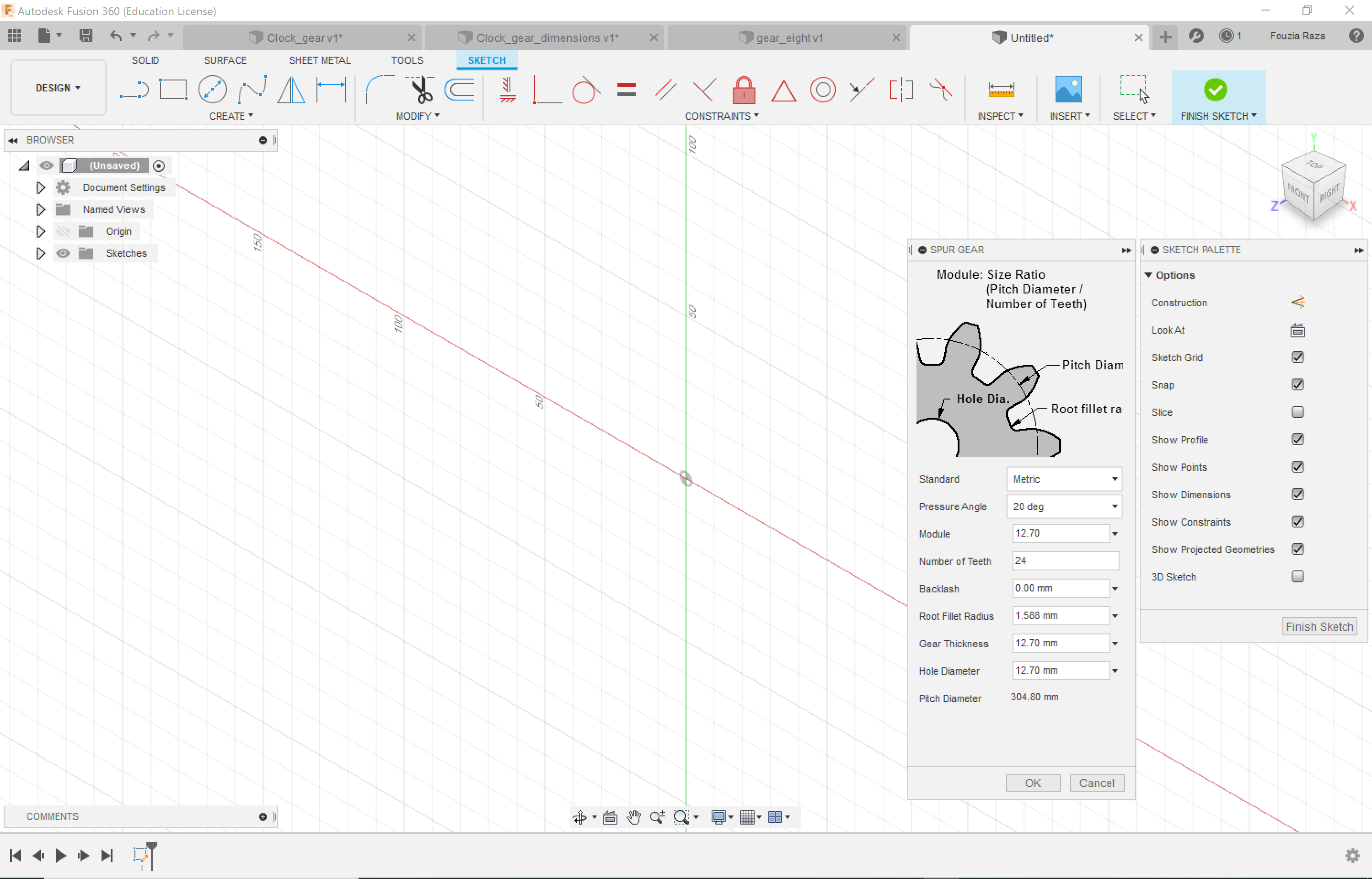
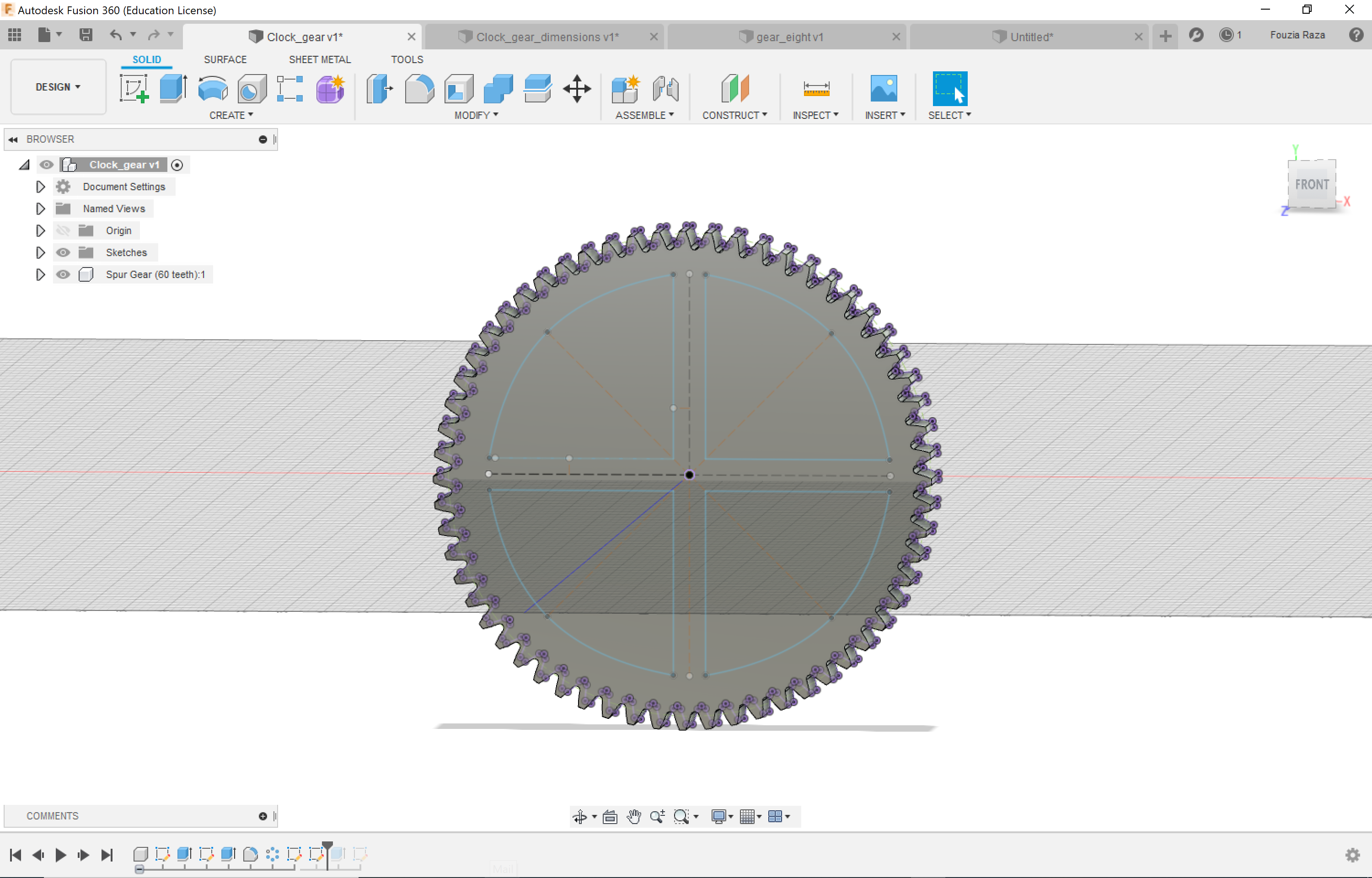
Using Fusion 360, I created the spur gears -- four large ones for the clock faces and three smaller driving gears. Using the add-ins feature, I created the larger spur gears by setting the following parameters:

Pressure angle: 20 degrees
Module: 2.0
Fillet radius: 0.5
Gear thickness: 12.70 mm
Number of teeth: 60
Pitch diamter: 120.00 mm

For the smaller gears, I used the following parameters:

Pressure angle: 20 degrees
Module: 1.0
Fillet radius: 0.3
Gear thickness: 12.70 mm
Number of teeth: 8, 7 or 10
Pitch diamter: 35.00 mm

Image

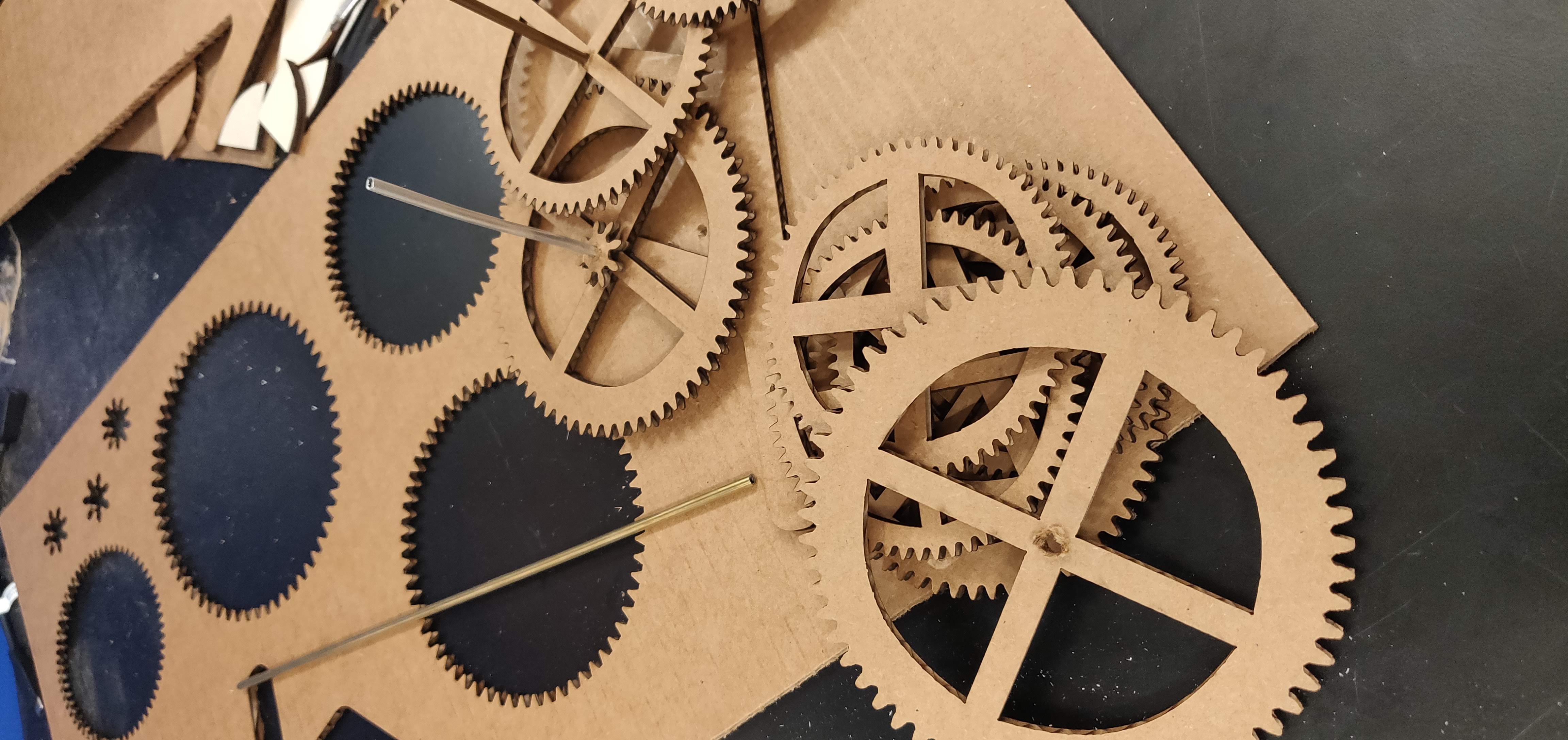
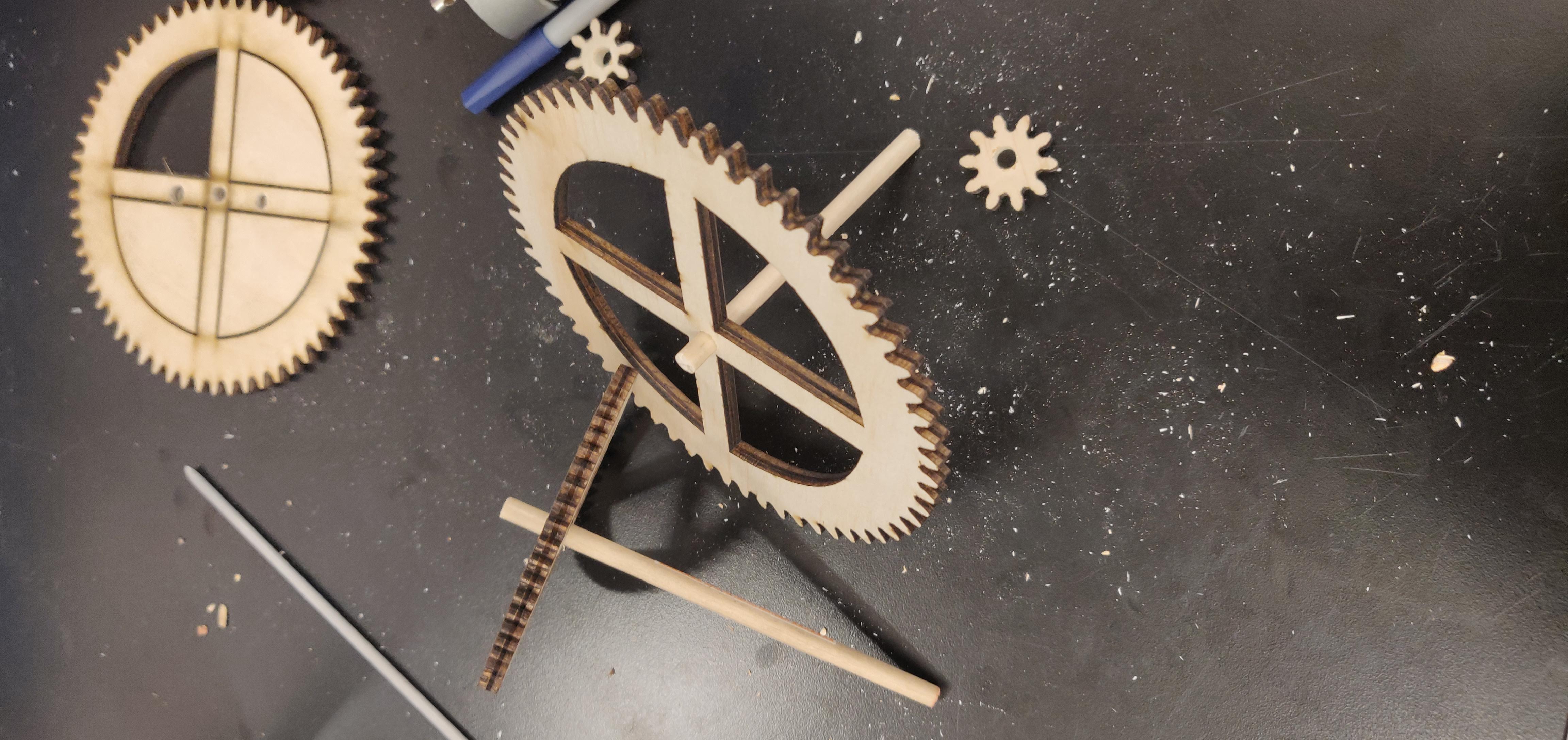
For stylistic purposes, I sketched windows into the gears using the line and mirror tools to make symmetrical cutouts around the construction lines marking the diameters of the gears.

Image

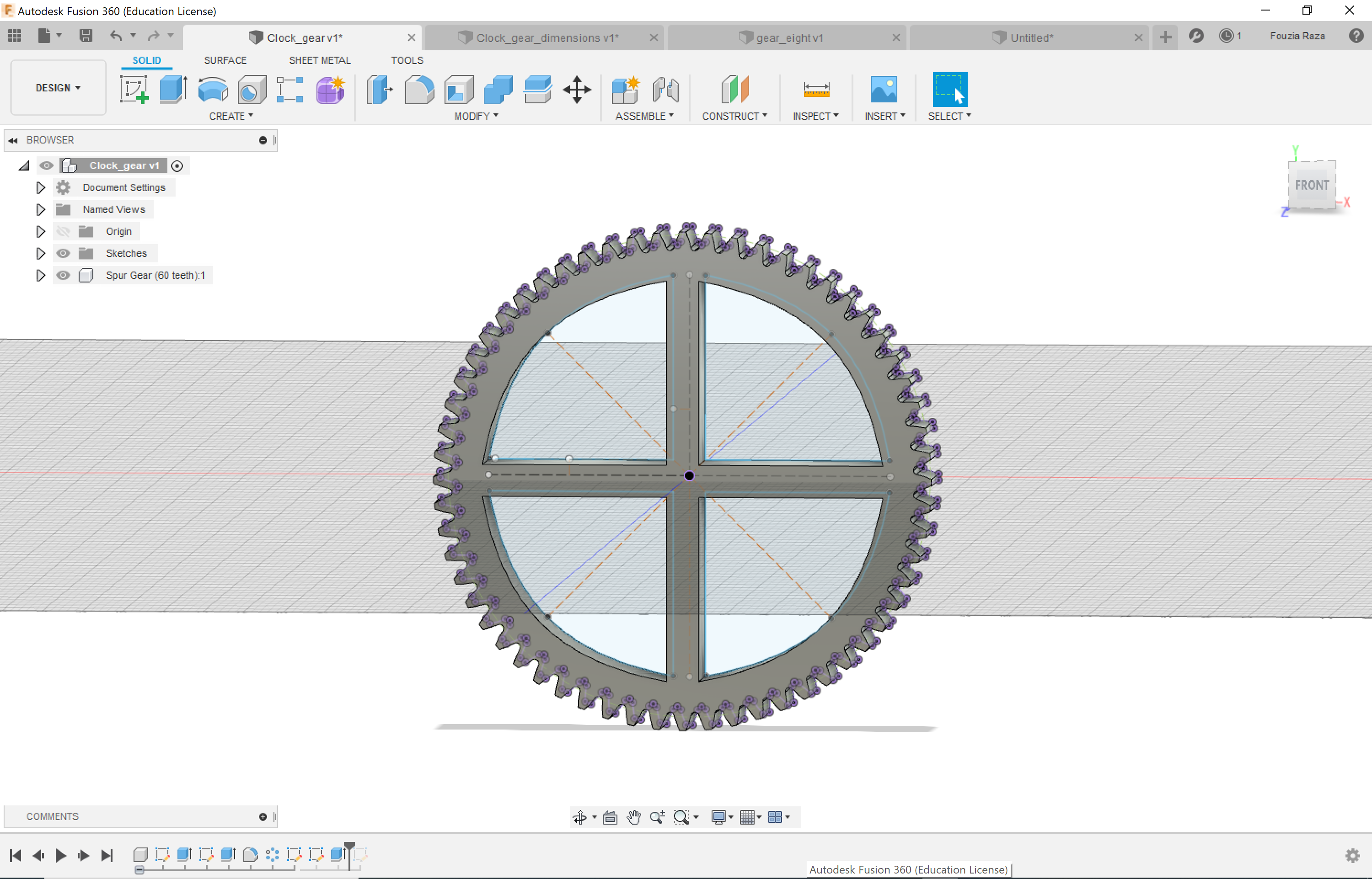
I then extruded the cutouts of my sketch and subtracted them from my gears. I did this with all of the larger gears and sped up the process by creating variables in my parameter space and chagning the dimensions for the different sizes.

Image

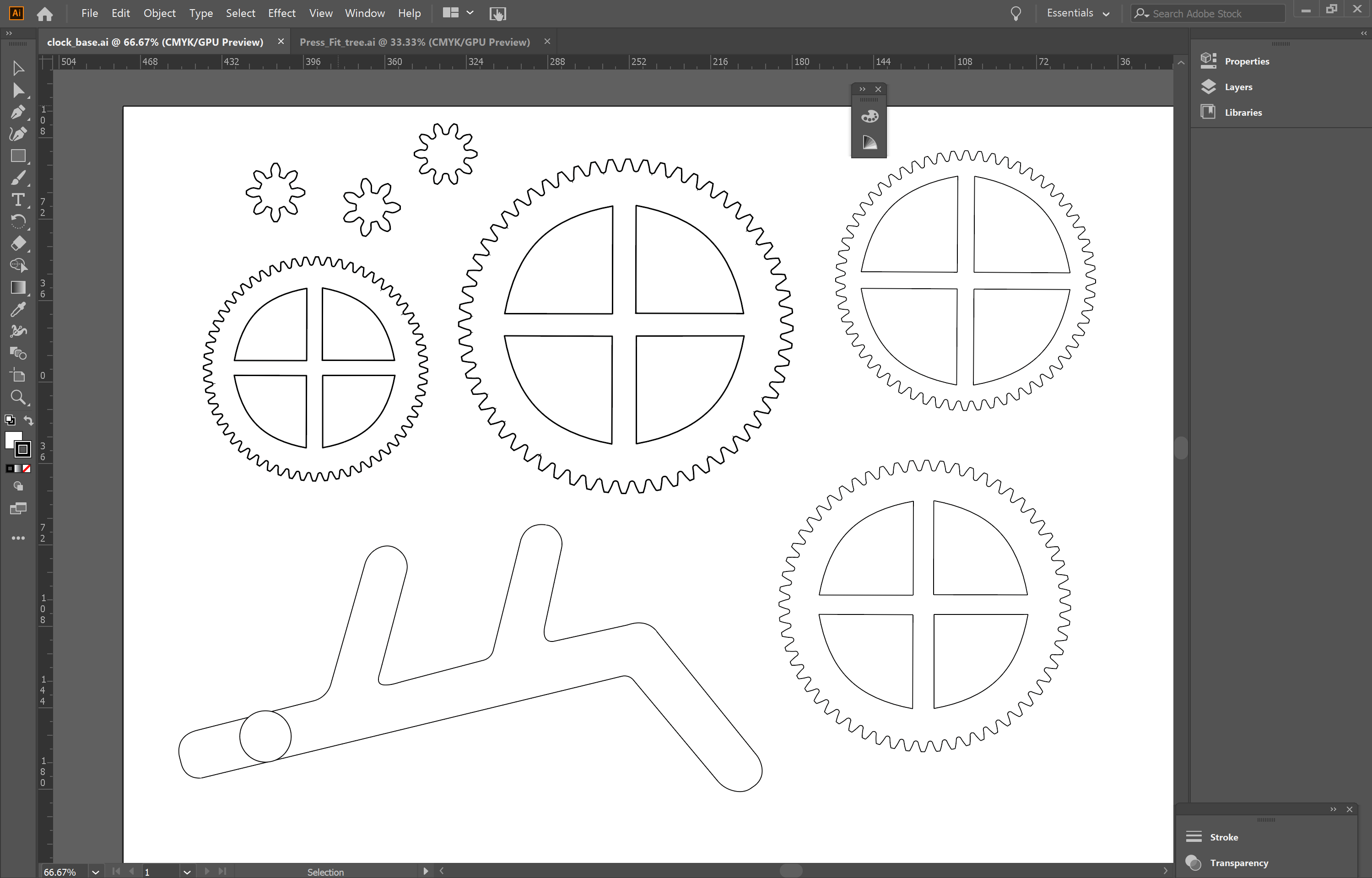
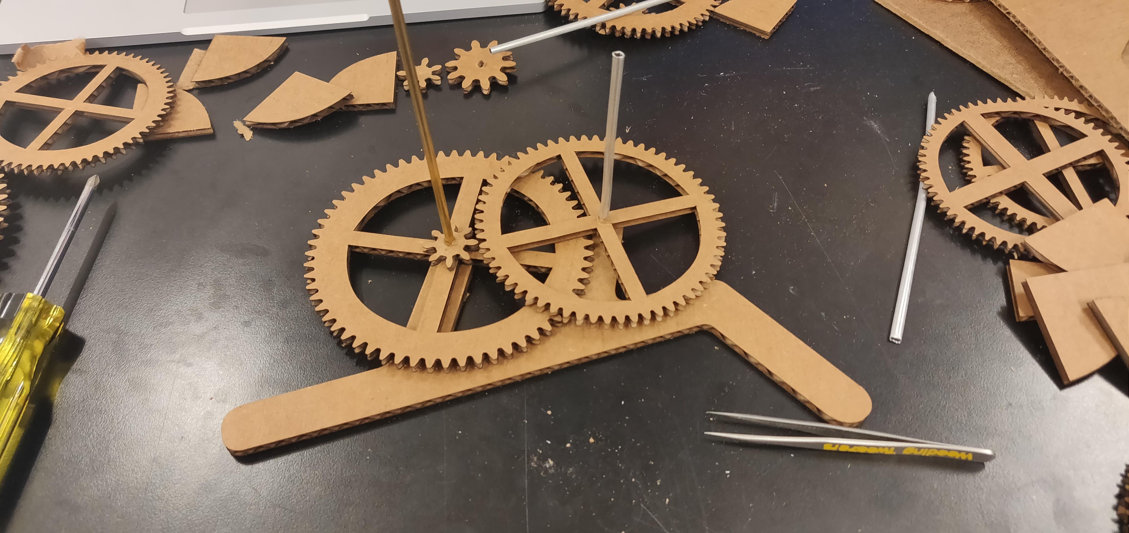
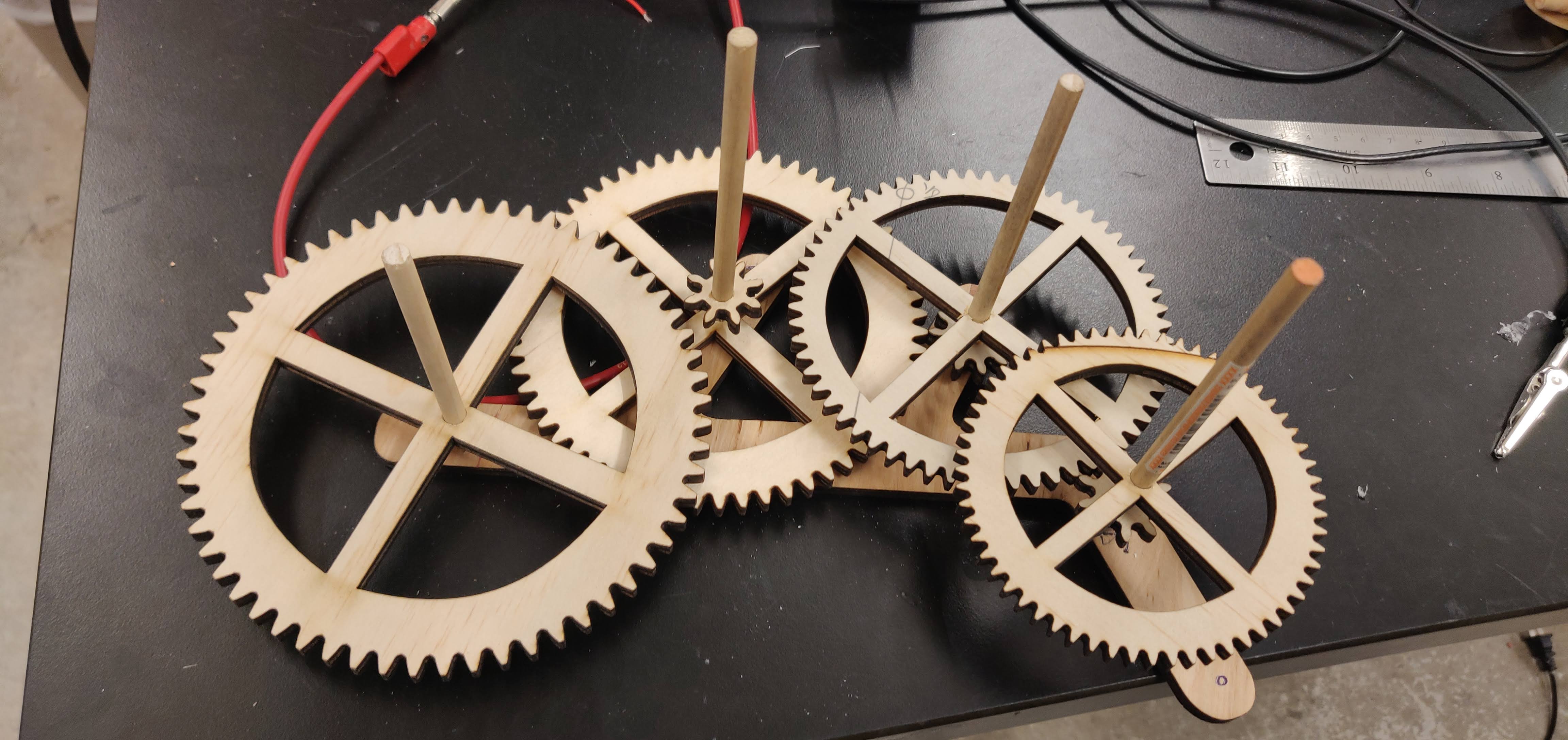
I then transferred the gears onto Illustrator and created the stand using the pen tool. To keep consistent with the Genesis clock design, I designed the shape of the stand to be quite similar to the original to allow for consistent gear and stand ratios. The merging of the files was a bit painful since Illustrator was not reading my STL file properly but thanks to Victoria, I was able to copy over my design by first making it into an image through Inkscape and then exporting the outlines. I first eyeballed the size of the gears before taking the measurements of the versions docummented online. This turned out be pretty accurate but all of it was done in Illustrator -- stick to Fusion kids, it's more accurate and a lot easier to use once you get the hang of it.

The gear ratios that were used: 7:60, 2:15, 1:6 with the first driving the second hand gear, the second driving the minute gear and the last rotating the hour gear.


lasercutgif

Before transferring the design onto wood, I first needed to make a working prototype using cardboard. After laser cutting all of the parts, I made holes in the middle of the gears to insert brass and aluminum rods for the axels for testing. I really could not find any other type of material in the lab and these rods were easy to roate the gears around so they had to do for now.

lasercutgif

Just to check whether the gears would turn each other, I set up a rough assembly (a small subset of the original design) and tested their rotation by rotating the larger gear on the right. They were turning! The assembly was a bit difficult with cardboard which unsurprisingly was too fragile for the small driving gears.


lasercutgif

To make the assembly process a little easier to understand, I labeled the gears in the above Illustrator file and will be referring to them in the following procedure. Starting from the right-most hole:

1. Gear 7 goes below gear 1
2. Gear 5 goes below gear 3, with gear 7 driving gear 3
3. Gear 6 goes above gear gear 4, with gear 5 driving gear 4
4. Gear 2 on the left-most hole, driven by gear 6


As this image shows, it was difficult to get all of the gears to move by rotating one gear. Although torque is not provided in the gear that I am rotating in the image (it's in the gear to the far right), the test was quite disheartening even after spending a couple of hours trying to make it work (chaning the sizes of the gears, recutting the pieces). So I just decided to move onto wood, hoping for the best. Definitely not good engineering practice but it had to be done...


Note to self: the size of the holes made on the stand and through each of the gears has to be identical to the diameter of the rods for a snug fit.

lasercutgif


lasercutgif
lasercutgif
lasercutgif

Onto wood! Due to the limited options, I used what was on hand in the shop (quarter inch thick for the gears). I decided to make the small driving gears out of acryllic and the rest of the parts out of wood. Although I wanted to used aluminum for the dowels, the lack of variety forced me into using wood instead. Increased friction between the dowel and the gear made it a bit difficult to rotate the gears but it could still generate enough torque to rotate the touching gears (surprisingly).

Using a quarter inch drill bit, I made holes in the center of each gear (or at least tried to aim for the center with the drill) and inserted 1/4 in dowels in each of the four larger gears, adding the driving gears in the necessary locations.

As you will see later on, my inability to drill holes at the precise center of the smaller gears made the rotations even less symmetrical, therefore making the clock even less accurate (the larger gears would turn only after a complete revolution of the smaller gear after having touching one of the teeth of the larger gears instead of a continuous, smooth rotation).


Now came the hard part -- making it move. So the major problem I had was not hitting the center of the driving gears with the hand drill and because of this the gear would come out too short for part of the rotation, causing the minute gear to stop rotating. So sure, this thing does move, but don't use it to tell time!

To see if the revolutions would be any smoother with a motor, I inserted the larger seconds gear on the right onto the motor shaft and tried rotating the second gear (from left) as a test. Surprisingly, all of the gears began rotating except for the hour gear (alt left) due to the poor drilling hole made on the left-most driving gear as seen in the GIF on the right.

As usual, however, there was a problem with the motor. After soldwering the wires, the motor shaft turned out to be too thin for the pure excuse of a collar I was using to connect the shaft and the wooden dowel. I worked around this by adding tape to the shaft and inserting it into the second hand gear directly (without the gear reduction, hence the fast rotation of the minute hand gear -- time surely flies fast!).

Image
Image


And walla! The finished product (with labeled numbers):


motor